did-you-know? rent-now

Amazon no longer offers textbook rentals. We do!

did-you-know? rent-now

Amazon no longer offers textbook rentals. We do!

We're the #1 textbook rental company. Let us show you why.

9781119156642

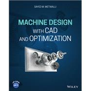
Machine Design with CAD and Optimization

by
  • ISBN13:

    9781119156642

  • ISBN10:

    1119156645

  • Edition: 1st
  • Format: Hardcover
  • Copyright: 2021-04-19
  • Publisher: Wiley
  • Purchase Benefits
  • Free Shipping Icon Free Shipping On Orders Over $35!
    Your order must be $35 or more to qualify for free economy shipping. Bulk sales, PO's, Marketplace items, eBooks and apparel do not qualify for this offer.
  • eCampus.com Logo Get Rewarded for Ordering Your Textbooks! Enroll Now
List Price: $149.28 Save up to $23.28
  • Buy New
    $148.53
    Add to Cart Free Shipping Icon Free Shipping

    PRINT ON DEMAND: 2-4 WEEKS. THIS ITEM CANNOT BE CANCELLED OR RETURNED.

Supplemental Materials

What is included with this book?

Summary

MACHINE DESIGN WITH CAD AND OPTIMIZATION

A guide to the new CAD and optimization tools and skills to generate real design synthesis of machine elements and systems

Machine Design with CAD and Optimization offers the basic tools to design or synthesize machine elements and assembly of prospective elements in systems or products. It contains the necessary knowledge base, computer aided design, and optimization tools to define appropriate geometry and material selection of machine elements. A comprehensive text for each element includes: a chart, excel sheet, a MATLAB® program, or an interactive program to calculate the element geometry to guide in the selection of the appropriate material.

The book contains an introduction to machine design and includes several design factors for consideration. It also offers information on the traditional rigorous design of machine elements. In addition, the author reviews the real design synthesis approach and offers material about stresses and material failure due to applied loading during intended performance. This comprehensive resource also contains an introduction to computer aided design and optimization. This important book:

  • Provides the tools to perform a new direct design synthesis rather than design by a process of repeated analysis
  • Contains a guide to knowledge-based design using CAD tools, software, and optimum component design for the new direct design synthesis of machine elements
  • Allows for the initial suitable design synthesis in a very short time
  • Delivers information on the utility of CAD and Optimization
  • Accompanied by an online companion site including presentation files

Written for students of engineering design, mechanical engineering, and automotive design. Machine Design with CAD and Optimization contains the new CAD and Optimization tools and defines the skills needed to generate real design synthesis of machine elements and systems on solid ground for better products and systems.
Author Biography

SAYED M. METWALLI, is Professor Emeritus of Machine Design and past Chair of Mechanical Design and Production Department, Cairo University, Egypt. He received a BS (Mech. Eng.) with honor from Cairo University (1965) and MS and PhD (Mech. Eng.) from State University of New York at Buffalo, USA, (1970) and (1973) respectively. Metwalli has conducted research and taught at North Carolina State University, the University of Central Florida, USA, and Kuwait University, and holds a US patent. His research interests are in design optimization theory, developing algorithms, and CAD/CAM software, with particular emphasis on optimum synthesis of mechanical components and systems including dynamics and controls for multitude of applications. He has conducted sponsored research with DOD/NRL, UNESCO, IBM-UK, NSF, EPA, USAID, and CU and has published more than 150 papers in journals and peer reviewed international conferences. His work with various manufacturers successfully implemented CAD and design optimization in their product design and development. He is an ASME Life Fellow, registered mechanical design consultant, and has been a registered PE in Florida.

Table of Contents

MACHINE DESIGN WITH CAD & OPTIMIZATION

CONTENTS:

NOMENCLATURE

PART 1

INTRODUCTION & DESIGN CONSIDERATIONS

1.            INTRODUCTION TO DESIGN

1.1.         Introduction

1.2.         Phases of Design

1.3.         Basic Mechanical Functions

1.4.         Design Factors

A.            Performance

B.            Constructional details

C.            Safety and reliability

D.            Cost and economy

1.5.         Synthesis Approach to Design

1.6.         Product Life Cycle

1.7.         Business Measures

1.8.         Research and Development Process in Product Cycle

1.9.         Teamwork for Product or System Design

1.10.      Design and Development Case Study.

1.11.      Units and Fundamentals

1.11.1.                   Units

1.11.2.                   Unit conversion

1.11.3.   Vectors and Matrices

1.12.      Summary

1.13.      References

1.14.      Problems

2.            DESIGN CONSIDERATIONS

2.1.         Mathematical Modeling

2.1.1.     Mathematical model initiation and adoption 

2.1.2.     Generalized system modeling

A.  Generalized variables

B.  Two terminal components

C.  Multi-terminal components

2.1.3.     Modeling of loading and material variations

2.2.         Calculation Tools

2.2.1.     Excel

2.2.2.     MATLAB

2.2.3.     Computer aided design (CAD)

2.2.4.     Finite Element (FE)

2.3.         Design Procedure

2.4.         Manufacturing Processes

2.4.1.     Casting or molding

2.4.2.     Deformation

2.4.3.     Machining

2.4.4.     Joining

2.4.5.     Surface and heat treatment

2.4.6.     3D printing or additive manufacturing

2.4.7.     Tolerances, surface finish, and fits

2.5.         Standard Sets and Components

2.6.         Codes and Standards

2.7.         Summary

2.8.         References

2.9.         Problems

PART 2

KNOWLEDGE-BASED DESIGN

3.            INTRODUCTION TO COMPUTER AIDED TECHNIQUES

3.1.         CAD and Geometric Modeling

3.1.1.     Classical design process

3.1.2.     Synthesis design process

3.1.3.     Human-machine characteristics

3.2.         Geometric Construction and FE Analysis

3.3.         CAD/CAM/CAE and Advanced Systems

3.4.         Virtual Reality

3.4.1.     Virtual reality process

3.4.2.     Virtual reality hardware requirements

3.4.3.     Virtual reality interactive process tools

3.4.4.     Virtual reality applications

3.5.         Summary

3.6.         References

3.7.         Problems

4.            COMPUTER AIDED DESIGN

4.1.         3-D Modeling and Transformation

4.1.1.     3D geometric modeling

A.            Geometric computations

B.            Topological operations and the Euler formula

C.            Geometric and global operations

D.            Procedures for constructing a single solid

4.1.2.     Homogeneous coordinates versus Cartesian coordinates

A.            Point in Space:

B.            Vectors

C.            Lines:

D.            Body geometry and vertices

4.1.3.     Body transformation

A.            Translation

B.            Rotation

C.            Scaling

D.            Zooming

E.            Skewing

F.            Perspective

G.           Orthographic projection

H.            Body transformation systems

4.1.4.     Stereo viewing

4.1.5.     3D graphics

4.2.         Parametric Modeling

4.2.1.     Parametric lines

4.2.2.     Parametric planes

4.2.3.     Parametric bilinear surfaces

4.2.4.     Parametric curves and surfaces

4.2.5.     Free form parametric curves and surfaces

A.            Surface patches and curves

B.            Bezier curves

C.            Bezier surfaces or patches

D.            B-spline curves

E.            B-spline surfaces

F.            NURBS

4.2.6.     Intersections

A.            Intersection of two lines

B.            Intersection of a line with a plane

C.            Intersection of two planes

D.            Intersection of three planes

4.3.         CAD Hardware and Software

4.4.         Rendering and Animation

4.4.1.     Realistic presentations

4.4.2.                     Color use

A.  Visual color description

B.  Color specification system

4.4.3.     Shading and rendering technique

4.4.4.     Computing vertex and surface normals

4.4.5.     Rendering process

A.            Diffuse illumination

B.            Specular reflection

C.            Transparency

D.            Total rendering effect 

4.4.6.     3D cursor and picking

4.5.         Data Structure

4.5.1.     Drawing exchange format DXF

4.5.2.     STL file format

4.5.3.     IGES file format

4.5.4.     STEP file format

4.6.         Using CAD in 3D Modeling and CAM

4.7.         Summary

4.8.         References

4.9.         Problems

5.            OPTIMIZATION

5.1.         Introduction

5.1.1.     Example 5.1. “A sample demonstration problem”

5.1.2.     Formulation of optimization problem

i.  Design Vector D

ii.  Objective Function f

iii.  Constraints

iv.  Problem statement

v.  Dimensional considerations in analytical design “Nondimensionalization”

5.1.3.     Example 5.2, “Nondimensionalization from governing equations” 

5.1.4.     Classification of optimization 

A.  Problem classification

B.  Methods of optimization

C.  Optimization fields

5.2.         Searches in One Direction

5.2.1.     Quadratic Interpolation

5.2.2.     Golden Section (Euclid)

5.2.3.     Newton-Raphson

5.2.4.     Other Methods

5.3.         Multi-Dimensional Classical Indirect Approach

5.3.1.     Unconstrained problem 

5.3.2.     Equality constrained problem

5.3.3.     Inequality constraints problem

5.4.         Multi-Dimensional Unconstrained Problem

5.4.1.     Univariate method

5.4.2.     Powell's method of conjugate directions

5.4.3.     Linearized ridge path method 

5.4.4.     Random search methods

5.4.5.     Steepest descent method

5.4.6.     Fletcher-Reeves conjugate gradient

5.4.7.     Newton-Raphson method

5.4.8.     Quasi-Newton methods

A.  A quadratic optimization technique

B.  Identified-quadratic optimization technique

5.4.9.  Comparison of unconstrained optimization methods

5.5.         Multi-Dimensional Constrained Problem

5.5.1.     Eliminating constraints by transformation

5.5.2.     Exterior penalty functions

5.5.3.     Interior penalty functions 

5.5.4.     Direct methods for constrained problems

A.  Convex–Concave property   

B.  Kuhn-Tucker conditions

C.  Gradient projection method

D.  Heuristic gradient projection method, HGP

E.  Constrained optimization samples

5.5.5.     Comparison of optimum constrained methods

5.6.         Applications to Machine Elements and Systems

5.7.         Summary

5.8.         References

5.9.         Problems

6.            STRESSES AND DEFLECTION

6.1.         Loads, Shear, Moment, Slope, and Deflection

6.1.1.     External and internal loads

6.1.2.  Pure bending

6.1.3.  Beam deflection 

A.  Deflection by integration 

B.  Deflection by superposition

C.  Deflection by singularity function

D.  Deflection by other methods

6.1.4.  Simple beam synthesis

6.1.5.  Comparing stresses and deflection in beams

A.  Beam stresses,

B.  Beam deflection,

C.  Equivalent loads on simple beams

6.2.         Mathematical Model 

6.3.         Simple Stresses

6.3.1.     Uniform tension and compression

6.3.2.     Direct uniform shear

6.3.3.     Pure bending

6.3.4.     Shear stress and deformation due to torsion

6.3.5.     Transverse shear and shear flow

6.4.         Combined Stresses

6.4.1.     Plane stress state

6.4.2.     Triaxial stress state 

6.4.3.     Applications in plane stress and triaxial stress states

i.  Thin pressure cylinders

ii.  Thick pressure cylinders

iii.  Press and shrink fits

iv.  Contact stresses

6.5.         Curved Beams

6.6.         Strain Energy and Deflection

6.6.1.     Elastic strain

6.6.2.     Elastic strain energy

6.6.3.     Castigliano’s theorem and deflections

6.7.         Columns

6.7.1.     Concentric loading 

6.7.2.     Eccentric loading

6.8.         Equivalent Element

6.9.         Thermal Effects

6.10.      Stress Concentration Factors

6.11.      Finite Element Method

6.11.1.   Axially loaded elements

6.11.2.   Prismatic beam element

6.11.3.   Constant strain triangle

6.11.4.   General 3D state - Linear elasticity problem

6.11.5.   General 3D-FE procedure

6.11.6.   Errors in FE modeling and solution 

6.11.7.   Some classical FE packages 

6.12.      Computer Aided Design and Optimization

6.12.1.   Beam synthesis tablet 

6.12.2.   Column synthesis tablet 

6.12.3.   Optimum stress concentration

6.12.4.   Optimum FE prismatic beams 

6.12.5.   Optimum FE cantilever beams

6.13.      Summary

6.14.      References

6.15.      Problems

7.            MATERIALS STATIC AND DYNAMIC STRENGTH

7.1.         Material Structure and Failure Modes

7.1.1.     Basic elements of material

7.1.2.     Material failure modes and properties

7.1.3.     Tensile properties 

7.1.4.     Other static properties

7.1.5.     Other time-dependent properties

7.2.         Numbering Systems and Designations

7.2.1.     Carbon and alloy steels

7.2.2.     Aluminum and aluminum alloys

7.2.3.     Other alloys

7.3.         Heat Treatment and Alloying Elements

7.3.1.     Heat treatment

7.3.2.     Case hardening

7.3.3.     Effect of alloying elements

7.4.         Material Propertied and General Applications

7.4.1.     Cast iron

7.4.2.     Plain and low-alloyed carbon steels

i.  Hot rolled and cold drawn plain-carbon steels

ii. Strength and hardness of annealed and normalized plain-carbon steels

iii. Quenched and tempered plain-carbon steels

iv. Quenched and tempered low-alloy steels

7.4.3.     Structural steel 

7.4.4.     Stainless steel 

7.4.5.     Tool steel 

7.4.6.     Other nonferrous metals             

i.  Aluminum and aluminum alloys,

ii. Copper and Magnesium alloys

7.4.7.     Other materials

i.  Plastics

ii. Composites 

7.5.         Particular Materials for Machine Elements

7.5.1.     Standard machine elements 

7.5.2.     Synthesized or designed machine elements

7.6.         Hardness and Strength 

7.7.         Failure and Static Failure Theories

7.7.1.     Maximum normal stress theory

7.7.2.     Maximum shear stress theory

7.7.3.     Maximum distortion energy theory (von Mises)

7.7.4.     Other failure theories

7.7.5.     Comparison and applications of failure theories

7.8.         Fatigue Strength and Factors Affecting Fatigue

7.8.1.     Fatigue strength

7.8.2.     Factors affecting fatigue strength

7.8.3.     Cumulative fatigue strength

7.8.4.     Fluctuating stresses

7.8.5.     Fatigue failure criteria   

7.9.         Fracture Mechanics and Fracture Toughness

7.9.1.     Stress intensity factor KI 

7.9.2.     Fracture toughness – critical stress intensity factor KIC 

7.9.3.     Crack propagation and life 

7.9.4.     Crack propagation and real case study

7.10.      Computer Aided Selection and Optimization

7.10.1.   Material properties – carbon steel 

7.10.2.   Fatigue strength and factors affecting fatigue – carbon steel 

7.10.3.   Static strength and factors of safety – carbon steel 

7.10.4.   Optimization for a specific factor of safety – carbon steel

7.11.      Summary

7.12.      References

7.13.      Problems

8.            INTRODUCTION TO ELEMENTS AND SYSTEM SYNTHESIS

8.1.         Introduction

8.2.         Basic and Common Machine Elements

8.2.1.     Couplings

i.  Rigid couplings

ii.  Flexible couplings

iii. Universal joints

8.2.2.     Keys, pins, retaining rings, and splines

i.  Keys

ii. Pins and cotter pins

iii. Retaining rings

iv. Splines

8.2.3.     Seals

8.2.4.                     Housings, enclosures, frames, and chassis

8.3.         Reverse Engineering

8.4.         Sample Applications

8.4.1.     Initial bolt synthesis

8.4.2.     Initial shaft synthesis 

8.4.3.     Initial bearing synthesis

8.5.         Computer Aided Design

8.6.         System Synthesis

8.7.         Computer Aided Assembly

8.8.           Summary

8.9.         References

8.10.      Problems

PART 3

DETAILED DESIGN OF MACHINE ELEMENTS

A.            BASIC JOINTS AND MACHINE ELEMENTS

9.            SCREWS, FASTENERS AND PERMANENT JOINTS

9.1.         Standards and Types

9.1.1.     Thread terminology and designation

9.1.2.     Joining alternative details

9.2.         Stresses in Threads

9.3.         Bolted Connections

9.3.1.     Threads under simple tensile load

9.3.2.     Preloading due to tightening 

9.3.3.     Tightening torque

9.4.         Strength in Static and Fatigue

9.5.         Power Screws

9.5.1.     Torque requirements

9.5.2.     Power screw efficiency

9.5.3.     Stresses in power screws

9.5.4.     Ball screws

9.6.         Permanent Joints

9.6.1.     Welding

9.6.2.     Bonded joints

9.7.         Computer Aided Design and Optimization

9.7.1.     Threads under simple tensile load

9.7.2.     Preloading due to bolt tightening

9.7.3.     Preloading, bolt tightening, and fatigue strength

9.7.4.     Power screws

9.7.5.     Permanent weldment joints

9.7.6.     Optimization

9.8.         Summary

9.9.         References

9.10.      Problems

10.          SPRINGS

10.1.      Types of Springs

10.2.      Helical Springs

10.2.1.   Geometry, definitions, and configurations

10.2.2.   Stresses and deflection

10.2.3.   Buckling

10.2.4.   Resonance

10.2.5.   Design procedure

10.2.6.   Extension springs

10.2.7.   Torsion springs

10.3.      Leaf Springs

10.3.1.   Stresses and deflection

10.3.2.   Design procedure

10.4.      Bellville Springs

10.5.      Elastomeric and Other Springs

10.6.      Computer Aided Design and Optimization

10.7.      Summary

10.8.      References

10.9.      Problems

11.          ROLLING BEARINGS

11.1.      Bearing Types and Selection

11.2.      Standard Dimension Series

11.2.1.   Boundary dimensions

11.2.2.   Bearing designation number

11.3.      Initial Design and Selection

11.4.      Bearing Load

11.4.1.   Bearing life and reliability

11.4.2.   Load distribution

11.4.3.   Bearing load rating

11.5.      Detailed Design and Selection

11.5.1.   Static loading

11.5.2.   Combined loading

11.5.3.   Tapered roller bearings

11.5.4.   Unsteady loading

11.5.5.   Detailed design procedure

11.6.      Speed limits

11.7.      Lubrication and Friction

11.8.      Mounting and Constructional Details

11.9.      Computer Aided Design and Optimization

11.9.1.   Initial ball bearing synthesis

11.9.2.   Dynamic load rating estimate

11.9.3.   Ball bearing selection

11.9.4.   Rolling bearing optimization

11.10.    Summary

11.11.    References

11.12.    Problems

12.          JOURNAL BEARINGS

12.1.      Lubricants

12.1.1.   Lubricant viscosity

12.1.2.   Lubricant selection

12.2.      Hydrodynamic Lubrication

12.2.1.   Petroff’s equation

12.2.2.   Journal bearings

A. Long bearing

B. Short bearing

C. Finite length bearing

12.3.      Journal Bearing Design Procedure

12.4.      Boundary and Mixed Lubrication

12.5.      Plain Bearing Materials

12.6.      Computer Aided Design and Optimization

12.6.1.   CAD of bearing synthesis using knowledge base practice

12.6.2.   CAD of bearing synthesis using an optimization approach

12.6.3.   Journal bearing synthesis tablet

12.7.      Summary

12.8.      References

12.9.      Problems

B.            POWER TRANSMITTING AND CONTROLLING ELEMENTS

13.          INTRODUCTION TO POWER TRANSMISSION AND CONTROL

13.1.      Prime Movers and Machines

13.2.      Collinear and Noncollinear Transmission Elements

13.3.      Power Control Elements

13.4.      Computer Aided Design of a Power Transmission System

13.5.      Summary

13.6.      References

13.7.      Problems

14.          SPUR GEARS

14.1.      Types and Utility

14.2.      Definition, Kinematics and Standards

14.3.      Force Analysis and Power transmission

14.4.      Design Procedure

14.4.1.   Classical Procedure

14.4.2.   Initial Synthesis

14.4.3.   Detailed Design

A. Material set

B. Bending fatigue

C. Surface fatigue

14.5.      Critical Speed

14.6.      Computer Aided Design and Optimization

14.7.      Constructional Details

14.7.1.   Gearboxes

14.7.2.   Gear trains

14.7.3.   Planetary or epicyclic gear trains

14.8.      Summary

14.9.      References

14.10.    Problems

15.          HELICAL, BEVEL AND WORM GEARS

15.1.      Helical Gears

15.1.1.   Types and Utility

15.1.2.   Definition, Kinematics and Standards

15.1.3.   Force Analysis

15.1.4.   Design Procedure

A. Initial synthesis

B. Detailed design

15.2.      Bevel Gears

15.2.1.   Definition, Kinematics and Standards

15.2.2.   Force Analysis

15.2.3.   Design Procedure

A. Initial synthesis

B. Detailed design

15.3.      Worm Gears

15.3.1.   Definition, Kinematics and Standards

15.3.2.   Force Analysis

15.3.3.   Design Procedure

A. Initial synthesis

B. Detailed design

15.4.      Gear Failure Regimes and Remedies

15.5.      Computer Aided Design and Optimization

15.5.1.   Helical gears synthesis

15.5.2.   Bevel gears synthesis

15.5.3.   Worm gears synthesis

15.6.      Constructional Details

15.7.      Summary

15.8.      References

15.9.      Problems

16.          FLEXIBLE ELEMENTS

16.1.      V BELTS

16.1.1.   V-belts Drive Relations

16.1.2.   Standards and Geometric Relations

16.1.3.   Design Procedure

A.  Initial Synthesis

B.  Detailed design process 

16.2.      FLAT BELTS

16.2.1.   Drive Relations

16.1.2.   Standards and Geometric Relations

16.1.3.   Design Procedure

A.  Initial synthesis

B.  Detailed design process 

16.3.      ROPES

16.3.1.   Sizes and Properties

A.  Wire rope strength

B.  Other wire rope properties

16.3.2.   Design Procedure

A.  Initial synthesis

B.  Detailed design process

16.4.      CHAINS

16.4.1.   Standards

A.            Chain size or number

B.            Chain sprockets

16.4.2.   Drive Relations

16.4.3.   Set Dimensions and Constraints 

16.4.4.   Design Procedure

A.            Initial synthesis

B.            Detailed design process 

16.5.      FRICTION DRIVES

16.6.      FLEXIBLE SHAFTS

16.7.      Computer Aided Design and Optimization

16.7.1.   V-belts synthesis 

16.7.2.   Wire rope synthesis

16.7.3.   Roller chains synthesis 

16.8.      Summary

16.9.      References

16.10.    Problems

17.          SHAFTS

17.1.      Types of Shafts and Axels

17.2.      Mathematical Model

17.3.      Initial Design Estimate

17.4.      Detailed Design

17.5.      Design for Rigidity

17.6.      Critical Speed

17.7.      Computer Aided Design and Optimization

17.7.1.   Shaft Materials

17.7.2.   Computer aided design of shafts

17.7.3.   Optimum design of shafts

17.8.      Constructional Details

17.9.      Summary

17.10.    References

17.11.    Problems

18.          CLUTCHES, BREAKS, AND FLYWHEELS

18.1.      Introduction and Classifications

18.2.      Cone Clutches and Brakes

18.2.1.   Uniform pressure

18.2.2.   Uniform wear rate

18.3.      Disk Clutches and Brakes

18.3.1.   Uniform pressure

18.3.2.   Uniform wear rate

18.3.3.   Multi-disk clutch-brake

A.            Uniform pressure

B.            Uniform wear rate

18.3.4.   Initial disk clutch-brake synthesis

18.4.      Caliper Disk Brakes

18.5.      Energy Dissipation and Temperature Rise

18.5.1.   Energy dissipation

18.5.2.   Temperature rise

18.6.      Design Process

18.6.1.   Initial synthesis

18.6.2.   Detailed design process

18.7.      Computer Aided Design and Optimization

18.8.      Flywheels

18.9.      Constructional Details

18.10.    Summary

18.11.    References

18.12.    Problems

APENDIXES 

A1.         Conversion between US and SI Units

A2.         Standard SI Prefixes

A3.         Preferred Numbers and Sizes

A4.         Standard Rods, or Bars

A5.         Standard Joining and Retaining Elements

A6.         Standard Sealing Elements

A7.         Material Properties

A8.         Standard Sections or Profiles and Section Properties

Supplemental Materials

What is included with this book?

The New copy of this book will include any supplemental materials advertised. Please check the title of the book to determine if it should include any access cards, study guides, lab manuals, CDs, etc.

The Used, Rental and eBook copies of this book are not guaranteed to include any supplemental materials. Typically, only the book itself is included. This is true even if the title states it includes any access cards, study guides, lab manuals, CDs, etc.

Rewards Program