rent-now

Rent More, Save More! Use code: ECRENTAL

5% off 1 book, 7% off 2 books, 10% off 3+ books

9781256873846

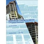
Reinforced Concrete Design A Practical Approach

by ;
  • ISBN13:

    9781256873846

  • ISBN10:

    1256873845

  • Edition: 2nd
  • Format: Hardcover
  • Copyright: 2012-10-23
  • Publisher: Pearson Learning Solutions
  • View Upgraded Edition
  • Purchase Benefits
  • Free Shipping Icon Free Shipping On Orders Over $35!
    Your order must be $35 or more to qualify for free economy shipping. Bulk sales, PO's, Marketplace items, eBooks and apparel do not qualify for this offer.
  • eCampus.com Logo Get Rewarded for Ordering Your Textbooks! Enroll Now
List Price: $173.60 Save up to $0.17
  • Buy New
    $173.43
    Add to Cart Free Shipping Icon Free Shipping

    USUALLY SHIPS IN 2-3 BUSINESS DAYS

Summary

Reinforced Concrete Design: A Practical Approach, 2E  is the only Canadian textbook which covers the design of reinforced concrete structural members in accordance with the CSA Standard A23.3-04 Design of Concrete Structures, including its 2005, 2007, and 2009 amendments, and the National Building Code of Canada 2010.


Reinforced Concrete Design: A Practical Approach covers key topics for curriculum of undergraduate reinforced concrete design courses, and it is a useful learning resource for the students and a practical reference for design engineers. Since its original release in 2005 the book has been well received by readers from Canadian universities, colleges, and design offices. The authors have been commended for a simple and practical approach to the subject by students and course instructors. The book contains numerous design examples solved in a step-by-step format. The second edition is going to be available exclusively in hard cover version, and colours have been used to embellish the content and illustrations.


This edition contains a new chapter on the design of two-way slabs and numerous revisions of the original manuscript. Design of two-way slabs is a challenging topic for engineering students and young engineers. The authors have made an effort to give a practical design perspective to this topic, and have focused on analysis and design approaches that are widely used in structural engineering practice. The topics include design of two-way slabs for flexure, shear, and deflection control. Comprehensive revisions were made to Chapter 4 to reflect the changes contained in the 2009 amendment to CSA A23.3-04. Chapters 6 and 7 have been revised to correct an oversight related to the transverse reinforcement spacing requirements in the previous edition of the book. Chapter 8 includes a new design example on slender columns and a few additional problems. Several errors and omissions (both text and illustrations) have also been corrected. More than 300 pages of the original book have been revised in this edition.


Several supplements are included on the book web site. Readers will get time-limited access to the new column design software BPA COLUMN, which can generate column interaction diagrams for rectangular and cicrcular columns of variable dimensions and reinforcement amount. Additional supplements include spreadsheets related to foundation design and column load take down, and a few Power Point presentations showcasing reinforced concrete structures under construction and in completed form. Instructors will have an access to additional web site, which contains electronic version of the Instructor's Solution Manual with complete solutions to the end-of-chapter problems, and Power Point presentations containing all illustrations from the book.


The book is a collaborative effort between an academic and a practising engineer and reflects their unique perspectives on the subject. Svetlana Brzev, Ph.D., P.Eng. is a faculty at the Civil Engineering Department of the British Columbia Institute of Technology, Burnaby, BC. She has over 25 years of combined teaching, research, and consulting experience related to structural design and rehabilitation of concrete and masonry structures, including buildings, municipal, and industrial facilities. John Pao, MEng, PEng, Struct.Eng, is the President of Bogdonov Pao Associates Ltd. of Vancouver, BC, and  BPA Group of Companies with offices in Seattle and Los Angeles.  Mr. Pao has extensive consulting experience related to design of reinforced concrete buildings, including high-rise residential and office buildings, shopping centers, parking garages, and institutional buildings.

 

Author Biography

Svetlana Brzev, Ph.D., P.Eng., is faculty in the Department of Civil Engineering of the British Columbia Institute of Technology (BCIT) in Vancouver, Canada. Dr. Brzev received her B.Eng. and M.A.Sc. degrees in Civil/Structural Engineering from the University of Belgrade, Serbia in 1894 and 1989 respectively, and a Ph.D. degree in Earthquake Engineering from the Indian Institute of Technology, Roorkee, India in 1994. She has over 25 years of combined teaching, research, and consulting experience related to structural and seismic design and rehabilitation of reinforced concrete and masonry buildings, municipal and industrial facilities. She is registered professional engineer in British Columbia. Her keen interest in teaching and sharing professional experience motivated her to join BCIT in 2000. She has developed and taught courses related to structural and seismic design of concrete and masonry structures. Her passion for teaching was recognized in 2011 through a BCIT teaching excellence award. Dr. Brzev is a member of two CSA Technical Committees responsible for developing national standards for masonry design and construction. She has co-authored a guide on seismic design of masonry structures and more than 80 papers and reports. She is actively involved in major international initiatives related to earthquake risk reduction, and has co-authored many publications on seismic safety of concrete and masonry buildings that have been translated in several languages. She is a member of the American Concrete Institute and the Masonry Society, and served as a Director and Vice-President of the Earthquake Engineering Research Institute.


John Pao, M.Eng., P.Eng., Struct.Eng.,S.E., is the President of Bogdonov Pao Associates Ltd. of Vancouver, Canada, and  BPA Group of Companies with offices in Seattle and Los Angeles. Mr. Pao received his B.A.Sc. and M.Eng. degrees in Civil Engineering from the University of British Columbia in 1980 and 1984 respectively. Mr. Pao has more than 30 years of experience related to structural design of high-rise residential and office buildings, shopping centers, sport arenas, parking garages, and institutional buildings. Mr. Pao's design projects involve a variety of structural materials, including reinforced and post-tensioned concrete, structural steel, wood, and masonry. His creative and innovative design approaches have won accolades from clients and colleagues from Canada and the United States. He is a licensed engineer in over twenty jurisdictions in the United States and Canada. His passions for structural design and engineering education have inspired him to give back to the profession and co-author this textbook. Mr. Pao has taught reinforced concrete design courses at various institutions since the mid-1980s. Along with a few colleagues, he pioneered the Certificate in Structural Engineering Program, a unique continuing education program for practicing structural engineers in British Columbia. He has served as the chair of the Organizing Committee for the program since its inception in 2001. The program has been very successful and has attracted students from across Canada and abroad.  Mr. Pao's knowledge and teaching experience related to design of reinforced concrete structures are reflected in this textbook for benefit of engineering students and practising engineers. 


Table of Contents

CHAPTER 1 CONCRETE BASICS 1

1.1 INTRODUCTION 1

1.2 CONCRETE AS A BUILDING MATERIAL 2

1.2.1 A Historical Overview 2

1.2.2 Concrete 3

1.2.3 Reinforced Concrete 3

1.2.4 Prestressed Concrete 5

1.3 REINFORCED CONCRETE BUILDINGS:

STRUCTURAL COMPONENTS AND SYSTEMS 6

1.3.1 Structural Components 6

1.3.2 Structural Systems 9

1.3.3 How Loads Flow Through a Building 10

1.4 DESIGN OF REINFORCED CONCRETE STRUCTURES 14

1.4.1 Design Considerations 14

1.4.2 Design Process 16

1.5 CONSTRUCTION OF REINFORCED CONCRETE STRUCTURES 17

1.5.1 Construction Process 17

1.5.2 Construction Methods 19

1.6 CANADIAN DESIGN CODES AND STANDARDS

FOR CONCRETE STRUCTURES 21

1.7 LOADS 21

1.7.1 Types of Loads 21

1.7.2 Dead Load 23

1.7.3 Live Load 24

1.7.4 Snow Load 24

1.7.5 Wind Load 25

1.7.6 Earthquake Load 25

1.7.7 Practical Considerations Related to Load Calculations 27

1.8 THE LIMIT STATES DESIGN METHOD 28

1.8.1 Limit States 28

1.8.2 Ultimate Limit States 28

1.8.3 Serviceability Limit States 31

Table of Contents

iii

000200010270803107_CH00_FM_pi-xxvi.qxd:Achorn Int'l 9/18/12 2:34 PM Page iii

1.8.4 Fire Resistance 31

1.8.5 Durability 32

1.9 ACCURACY IN DESIGN AND CONSTRUCTION 32

1.9.1 Research Studies Versus Real-Life Design Applications 32

1.9.2 Accuracy of Calculations 33

1.10 USE OF COMPUTER-AIDED DESIGN TOOLS 34

Summary and Review — Concrete Basics 36

Problems 39

CHAPTER 2 MATERIALS 41

2.1 INTRODUCTION 41

2.2 CONCRETE MATERIALS AND PRODUCTION 42

2.2.1 Portland Cement and Supplementary Materials 42

2.2.2 Water and Water-Cement Ratio 43

2.2.3 Air 44

2.2.4 Aggregates 44

2.2.5 Admixtures 45

2.2.6 Concrete Mix Design and Fresh Concrete 46

2.2.7 Hardened Concrete 46

2.3 PROPERTIES OF HARDENED CONCRETE 48

2.3.1 Compressive Strength 48

2.3.2 Tensile Strength 49

2.3.3 Shear Strength 50

2.3.4 Modulus of Elasticity 50

2.3.5 Creep 53

2.3.6 Shrinkage 55

2.3.7 Temperature Effects 58

2.3.8 Mass Density 58

2.3.9 Poisson’s Ratio 59

2.4 DURABILITY OF CONCRETE 59

2.5 FIRE-RESISTANCE REQUIREMENTS 61

2.6 REINFORCEMENT 62

2.6.1 Types of Reinforcement 62

2.6.2 Mechanical Properties of Steel 63

2.6.3 Deformed Bars 64

2.6.4 Welded Wire Fabric 66

Summary and Review — Materials 67

Problems 70

CHAPTER 3 FLEXURE: BEHAVIOUR OF BEAMS

AND ONE-WAY SLABS 72

3.1 INTRODUCTION 72

3.2 TYPES OF FLEXURAL MEMBERS 73

iv TABLE OF CONTENTS

000200010270803107_CH00_FM_pi-xxvi.qxd:Achorn Int'l 9/18/12 2:34 PM Page iv

3.3 GENERAL ASSUMPTIONS RELATED TO FLEXURE IN REINFORCED

CONCRETE BEAMS AND SLABS 75

3.3.1 Notation 75

3.3.2 Limit States Design Assumptions 76

3.3.3 Factored Material Strength 77

3.3.4 Equivalent Rectangular Stress Distribution

in Concrete 78

3.4 BEHAVIOUR OF REINFORCED CONCRETE BEAMS

IN FLEXURE 79

3.4.1 Unreinforced Beams 79

3.4.2 Reinforced Beams 80

3.4.3 Failure Modes Characteristic of Reinforced Concrete

Flexural Members 83

3.5 MOMENT RESISTANCE OF RECTANGULAR BEAMS

WITH TENSION STEEL ONLY 87

3.5.1 Properly Reinforced Beams (Steel-Controlled Failure) 87

3.5.2 Overreinforced Beams (Concrete-Controlled Failure) 90

3.5.3 Balanced Condition 95

3.6 FLEXURAL RESISTANCE OF ONE-WAY SLABS 101

3.6.1 One-Way and Two-Way Slabs 101

3.6.2 Moment Resistance of a One-Way Slab 103

3.7 T-BEAMS 107

3.7.1 Background 107

3.7.2 Flexural Resistance of T-Beams for Positive Bending 108

3.7.3 Flexural Resistance of T-Beams in Negative Bending 120

3.8 RECTANGULAR BEAMS WITH TENSION AND COMPRESSION

REINFORCEMENT 121

3.8.1 Background 121

3.8.2 Flexural Resistance of Doubly Reinforced Rectangular Beams 122

Summary and Review — Flexure: Behaviour of Beams

and One-Way Slabs 128

Problems 130

CHAPTER 4 SERVICEABILITY 134

4.1 INTRODUCTION 134

4.2 BEHAVIOUR OF REINFORCED CONCRETE FLEXURAL

MEMBERS UNDER SERVICE LOADS 135

4.3 PROPERTIES OF REINFORCED CONCRETE FLEXURAL

MEMBERS UNDER SERVICE LOADS 138

4.3.1 Flexural Stiffness 138

4.3.2 Moment of Inertia 140

4.3.3 Gross Moment of Inertia 140

4.3.4 Cracked Moment of Inertia 142

4.3.5 Effective Moment of Inertia 145

TABLE OF CONTENTS v

000200010270803107_CH00_FM_pi-xxvi.qxd:Achorn Int'l 9/18/12 2:34 PM Page v

4.4 DEFLECTIONS IN REINFORCED CONCRETE FLEXURAL MEMBERS 146

4.4.1 Background 146

4.4.2 Immediate Deflections 147

4.4.3 Long-Term Deflections 149

4.5 CSA A23.3 DEFLECTION CONTROL REQUIREMENTS 151

4.5.1 Background 151

4.5.2 Indirect Approach 151

4.5.3 Allowable Deflections 153

4.6 DEFLECTION CALCULATION PROCEDURES 153

4.6.1 Background 153

4.6.2 Deflections in Simply Supported Flexural Members 155

4.6.3 Deflections in Continuous Flexural Members 160

4.7 CAUSES OF CRACKING IN REINFORCED

CONCRETE STRUCTURES 173

4.7.1 Plastic Settlement 174

4.7.2 Shrinkage 174

4.7.3 Corrosion 175

4.7.4 Weathering 176

4.7.5 Structural Distress 176

4.7.6 Poor Construction Practices 176

4.7.7 Crack Width 177

4.8 CSA A23.3 CRACKING CONTROL REQUIREMENTS 177

4.8.1 Skin Reinforcement — Beams and Slabs 181

Summary and Review — Serviceability 183

Problems 186

CHAPTER 5 FLEXURE: DESIGN OF BEAMS

AND ONE-WAY SLABS 190

5.1 INTRODUCTION 190

5.2 GENERAL DESIGN REQUIREMENTS 191

5.3 DETAILING REQUIREMENTS 191

5.3.1 Concrete Cover 191

5.3.2 Bar Spacing Requirements 192

5.3.3 Computation of the Effective Beam Depth Based

on the Detailing Requirements 194

5.4 PRACTICAL GUIDELINES FOR THE DESIGN AND CONSTRUCTION

OF BEAMS AND ONE-WAY SLABS 196

5.4.1 Design Guidelines 196

5.4.2 Construction Considerations and Practices 199

5.5 DESIGN PROCEDURES FOR RECTANGULAR BEAMS

AND SLABS WITH TENSION STEEL ONLY 201

5.5.1 Direct Procedure 202

5.5.2 Iterative Procedure 205

vi TABLE OF CONTENTS

000200010270803107_CH00_FM_pi-xxvi.qxd:Achorn Int'l 9/18/12 2:34 PM Page vi

5.6 DESIGN OF RECTANGULAR BEAMS

WITH TENSION STEEL ONLY 208

5.6.1 CSA A23.3 Flexural Design Provisions for Rectangular Beams

with Tension Steel Only 208

5.6.2 Design of Rectangular Beams with Tension Steel Only:

Summary and a Design Example 212

5.7 DESIGN OF ONE-WAY SLABS 220

5.7.1 CSA A23.3 Flexural Design Provisions for One-Way Slabs 220

5.7.2 Design of One-Way Slabs: Summary and a Design Example 222

5.8 DESIGN OF T-BEAMS 230

5.8.1 CSA A23.3 Flexural Design Provisions for T-Beams 230

5.8.2 Design of T-Beams: Summary and a Design Example 232

5.9 DESIGN OF RECTANGULAR BEAMS WITH TENSION

AND COMPRESSION REINFORCEMENT 242

5.9.1 CSA A23.3 Flexural Design Provisions for Beams with Tension

and Compression Reinforcement 242

5.9.2 Design of Rectangular Beams with Tension and Compression

Reinforcement: Summary and a Design Example 243

Summary and Review — Flexure: Design of Beams

and One-Way Slabs 254

Problems 256

CHAPTER 6 SHEAR DESIGN OF BEAMS AND ONE-WAY SLABS 260

6.1 INTRODUCTION 260

6.2 BEHAVIOUR OF UNCRACKED CONCRETE BEAMS 261

6.3 BEHAVIOUR OF REINFORCED CONCRETE BEAMS

WITHOUT SHEAR REINFORCEMENT 264

6.3.1 Failure Modes 264

6.3.2 Shear Resistance of Cracked Beams 268

6.4 BEHAVIOUR OF REINFORCED CONCRETE BEAMS

WITH SHEAR REINFORCEMENT 270

6.4.1 Types of Shear Reinforcement 270

6.4.2 Effect of Shear Reinforcement 272

6.4.3 Truss Analogy for Concrete Beams Failing in Shear 273

6.4.4 Shear Resistance of Beams with Shear Reinforcement 275

6.5 SHEAR DESIGN ACCORDING TO CSA A23.3 277

6.5.1 General Design Philosophy 277

6.5.2 Simplified and General Methods for Shear Design 277

6.5.3 Major Revisions in CSA A23.3–04 278

6.5.4 CSA A23.3 Requirements Related to the Simplified Method

for Shear Design 278

6.6 SHEAR DESIGN CONSIDERATIONS 285

TABLE OF CONTENTS vii

000200010270803107_CH00_FM_pi-xxvi.qxd:Achorn Int'l 9/18/12 2:34 PM Page vii

6.7 SHEAR DESIGN OF REINFORCED CONCRETE BEAMS

ACCORDING TO THE CSA A23.3 SIMPLIFIED METHOD:

SUMMARY AND DESIGN EXAMPLES 288

6.8 SHEAR DESIGN OF SIMPLE ONE-WAY SLABS 304

6.9 DETAILING OF SHEAR REINFORCEMENT 306

6.10 SHEAR FRICTION (INTERFACE SHEAR TRANSFER) 308

6.10.1 Background 308

6.10.2 CSA A23.3 Design Requirements 309

Summary and Review — Shear Design of Beams and One-Way Slabs 313

Problems 314

CHAPTER 7 TORSION 318

7.1 INTRODUCTION 318

7.2 TORSIONAL EFFECTS 318

7.3 BEHAVIOUR OF CONCRETE BEAMS SUBJECTED TO TORSION 319

7.4 TORSIONAL RESISTANCE OF REINFORCED CONCRETE BEAMS 321

7.4.1 Background 321

7.4.2 Torsional Resistance of Concrete 322

7.4.3 Ultimate Torsional Resistance of a Cracked Beam 323

7.5 COMBINED TORSION, SHEAR, AND FLEXURE LOADS 326

7.5.1 Combined Shear and Torsion 326

7.5.2 Combined Flexure and Torsion 327

7.6 CSA A23.3 REQUIREMENTS FOR THE SIMPLIFIED METHOD

FOR TORSION DESIGN 329

7.7 DETAILING OF TORSIONAL REINFORCEMENT 331

7.8 TORSIONAL DESIGN CONSIDERATIONS 333

7.9 DESIGN FOR TORSION PER THE CSA A23.3 SIMPLIFIED

METHOD: SUMMARY AND A DESIGN EXAMPLE 334

Summary and Review — Torsion 344

Problems 345

CHAPTER 8 COLUMNS 347

8.1 INTRODUCTION 347

8.2 TYPES OF REINFORCED CONCRETE COLUMNS 348

8.3 MAIN COMPONENTS OF A REINFORCED CONCRETE COLUMN 349

8.3.1 Longitudinal Reinforcement 350

8.3.2 Transverse Reinforcement 350

8.3.3 Concrete Core 351

viii TABLE OF CONTENTS

000200010270803107_CH00_FM_pi-xxvi.qxd:Achorn Int'l 9/18/12 2:34 PM Page viii

8.4 COLUMN LOADS: CONCENTRICALLY VERSUS ECCENTRICALLY

LOADED COLUMNS 352

8.5 BEHAVIOUR OF REINFORCED CONCRETE SHORT COLUMNS 353

8.6 AXIAL AND FLEXURAL LOAD RESISTANCE

OF REINFORCED CONCRETE COLUMNS 357

8.6.1 Basic CSA A23.3 Column Design Assumptions 357

8.6.2 Axial Load Resistance of a Concentrically Loaded Short Column 357

8.6.3 Axial and Flexural Resistance of Eccentrically Loaded

Reinforced Concrete Short Columns 362

8.6.4 Column Load Resistance Corresponding

to the Balanced Condition 365

8.7 COLUMN INTERACTION DIAGRAMS 368

8.7.1 Key Features 368

8.7.2 Development of a Column Interaction Diagram 371

8.7.3 Use of Column Interaction Diagrams in Column Design Applications 374

8.8 CSA A23.3 COLUMN DESIGN REQUIREMENTS 383

8.8.1 Reinforcement Requirements 383

8.9 PRACTICAL DESIGN GUIDELINES 389

8.10 A GENERAL COLUMN DESIGN PROCEDURE 390

8.11 STRUCTURAL DRAWINGS AND DETAILS FOR REINFORCED

CONCRETE COLUMNS 395

8.12 INTRODUCTION TO SLENDER COLUMNS 397

8.12.1 Slenderness of Concrete Columns 397

8.12.2 Behaviour of Slender Columns—Instability Failures 399

8.12.3 When Slenderness Effects Should Be Considered 400

8.12.4 Analysis of Slender Columns in Nonsway Frames 401

8.13 COLUMN LOADS IN MULTISTOREY BUILDINGS 408

8.13.1 Tributary Area 408

8.13.2 Live Load Reductions 408

Summary and Review — Columns 411

Problems 413

CHAPTER 9 BOND AND ANCHORAGE OF REINFORCEMENT 416

9.1 INTRODUCTION 416

9.2 BOND IN REINFORCED CONCRETE FLEXURAL MEMBERS 417

9.3 DEVELOPMENT LENGTH OF STRAIGHT BARS 420

9.3.1 Background 420

9.3.2 Development Length of Straight Reinforcing Bars in Tension 421

9.3.3 Development Length of Straight Bars in Compression 426

9.4 STANDARD HOOKS IN TENSION 427

TABLE OF CONTENTS ix

000200010270803107_CH00_FM_pi-xxvi.qxd:Achorn Int'l 9/18/12 2:34 PM Page ix

9.5 HOOKS FOR STIRRUPS AND TIES 432

9.6 BAR CUTOFFS IN SIMPLY SUPPORTED FLEXURAL MEMBERS 434

9.6.1 Background 434

9.6.2 Theoretical Point of Cutoff 434

9.6.3 Bar Extensions 439

9.6.4 Bent Bars 440

9.7 ANCHORAGE DESIGN FOR FLEXURAL REINFORCEMENT

ACCORDING TO CSA A23.3 440

9.7.1 Revisions in CSA A23.3.04 440

9.7.2 General Anchorage Requirement 441

9.7.3 Actual Point of Cutoff 441

9.7.4 Development of Continuing Reinforcement 442

9.7.5 Development of Positive Moment Reinforcement at Supports 442

9.7.6 Anchorage of Negative Moment Reinforcement into

Supporting Members 442

9.7.7 Development of Negative Moment Reinforcement

at Inflection Points 443

9.7.8 Development of Positive Moment Reinforcement

at Zero Moment Locations 444

9.7.9 Flexural Tension Side 447

9.8 CALCULATION OF BAR CUTOFF POINTS IN SIMPLY

SUPPORTED FLEXURAL MEMBERS ACCORDING TO

THE CSA A23.3 REQUIREMENTS 449

9.9 SPLICES 456

9.9.1 Background 456

9.9.2 Tension Splices 457

9.9.3 Compression Splices 459

9.9.4 Column Splices 459

Summary and Review — Bond and Anchorage of Reinforcement 461

Problems 464

CHAPTER 10 BEHAVIOUR AND ANALYSIS OF CONTINUOUS

BEAMS AND SLABS 467

10.1 INTRODUCTION 467

10.2 FUNDAMENTAL CONCEPTS OF CONTINUOUS

REINFORCED CONCRETE STRUCTURES 468

10.2.1 Simple Versus Continuous Structures 468

10.2.2 Stiffness Distribution in Continuous Structures 470

10.3 LOAD PATTERNS 474

10.4 SIMPLIFICATIONS IN THE ANALYSIS OF REINFORCED

CONCRETE FRAME STRUCTURES 481

10.4.1 Actual Structure Versus Idealized Structural Model 481

10.4.2 Frame Model 481

10.4.3 Reduction of Bending Moments at the Supports 482

x TABLE OF CONTENTS

000200010270803107_CH00_FM_pi-xxvi.qxd:Achorn Int'l 9/18/12 2:34 PM Page x

10.5 ANALYSIS METHODS FOR CONTINUOUS REINFORCED

CONCRETE STRUCTURES 485

10.6 APPROXIMATE FRAME ANALYSIS 486

10.7 BEHAVIOUR OF CRACKED CONTINUOUS REINFORCED

CONCRETE FLEXURAL MEMBERS 492

10.7.1 Background 492

10.7.2 Elastic Versus Inelastic Behaviour 492

10.7.3 The Effect of Reinforcement Distribution

in the Postcracking Stage 493

10.8 ANALYSIS OF CRACKED CONTINUOUS REINFORCED

CONCRETE FLEXURAL MEMBERS 496

10.8.1 Background 496

10.8.2 Computer-Aided Iterative Analysis of Cracked Continuous

Reinforced Concrete Structures 497

10.9 MOMENT REDISTRIBUTION PROCESS ACCORDING TO CSA A23.3 502

Summary and Review — Behaviour and Analysis of Continuous

Beams and Slabs 508

Problems 509

CHAPTER 11 DESIGN OF CONTINUOUS BEAMS, SLABS,

AND FLOOR SYSTEMS 513

11.1 INTRODUCTION 513

11.2 FLOOR SYSTEMS IN CAST-IN-PLACE

CONCRETE CONSTRUCTION 515

11.2.1 Background 515

11.2.2 One-Way Joist Floor System 515

11.2.3 Slab-Beam-and-Girder Floor System 517

11.2.4 Slab Band Floor System 521

11.2.5 Cost Considerations 523

11.3 A DESIGN CASE STUDY OF A SLAB-AND-BEAM FLOOR SYSTEM 524

11.4 DETAILING OF FLEXURAL REINFORCEMENT

IN CONTINUOUS BEAMS AND SLABS 547

11.4.1 Background 547

11.4.2 Bar Cutoffs in Continuous Members According to the CSA A23.3

Requirements 548

11.4.3 Practical Detailing Considerations for Flexural Reinforcement

in Continuous Beams and Slabs 565

11.5 STRUCTURAL DRAWINGS AND SPECIFICATIONS 567

11.5.1 Background 567

11.5.2 Sample Drawings for the Floor Design Case Study 570

Summary and Review — Design of Continuous Beams, Slabs,

and Floor Systems 573

Problems 574

TABLE OF CONTENTS xi

000200010270803107_CH00_FM_pi-xxvi.qxd:Achorn Int'l 9/18/12 2:34 PM Page xi

CHAPTER 12 DESIGN OF TWO-WAY SLAB 578

12.1 INTRODUCTION 578

12.2 TYPES OF TWO-WAY SLABS 579

12.2.1 Background 579

12.2.2 Flat Plates 580

12.2.3 Flat Slabs 582

12.2.4 Waffle Slabs 582

12.2.5 Slabs with Beams 585

12.3 BEHAVIOUR TWO-WAY SLABS SUBJECTED TO FLEXURE 586

12.3.1 Background 586

12.3.2 Gravity Load Paths in Two-Way Slabs 589

12.3.3 Distribution of Bending Moments in Two-Way Slabs 592

Statics-Based Approach for Estimating Bending Moments

in Two-Way Slabs 592

Bending Moments in Slabs with Beams 595

12.3.4 Moment Redistribution in Cracked Two-Way Slabs 595

12.3.5 Design for Flexure According to CSA A23.3 598

12.4 DEFINITIONS 598

12.4.1 Design Strip 598

12.4.2 Band Width (bb) 600

12.4.3 Clear Span 600

12.4.4 Effective Beam Section 600

12.4.5 Beam-to-Slab Stiffness Ratio (α) 601

12.5 GENERAL CSA A23.3 DESIGN PROVISIONS 602

12.5.1 Regular Two-Way Slab Systems 602

12.5.2 Minimum CSA A23.3 Slab Thickness Requirements for Deflection Control 603

Minimum Slab Thickness 603

Flat Plates 604

Flat Slabs (Slabs With Drop Panels) 605

Slabs with Beams Between All Supports 605

12.6 DESIGN FOR FLEXURE ACCORDING TO THE DIRECT DESIGN METHOD 607

12.6.1 Limitations 607

12.6.2 The Concept 607

12.6.3 Bending Moment Distribution in Flat Plates and Flat Slabs 610

12.6.4 Bending Moment Distribution in Slabs With Beams Between

all Supports 615

12.6.5 Unbalanced Moments 618

12.6.6 CSA A23.3 Reinforcement Requirements for Two-Way Slabs 621

Design of Flexural Reinforcement 621

Reinforcement Requirements for Flat Slabs and Flat Plates 621

Reinforcement Requirements for Slabs with Beams 625

12.6.7 Design Applications of the Direct Design Method 625

12.7 ELASTIC ANALYSIS 646

12.7.1 Background 646

12.7.2 Equivalent Frame Method 646

xii TABLE OF CONTENTS

000200010270803107_CH00_FM_pi-xxvi.qxd:Achorn Int'l 9/18/12 2:34 PM Page xii

Features 646

Equivalent Frames: Concept 647

Modelling of Equivalent Frame Members 649

Prismatic Approach for Modelling Frame Sections 654

Design Bending Moments at Supports 655

Arrangement of Live Load (Load Patterns) 656

Buildings with Two-Way Slab Systems: Gravity and Lateral

Load Analysis 657

Guidelines for Effective Modelling of Equivalent Frames 662

Design Applications of the Equivalent Frame Method 663

12.7.3 Three-Dimensional Elastic Analysis 679

The Concept 679

3-D Finite Element Analysis of Irregular Two-Way Slabs 685

12.8 YIELD LINE METHOD 689

12.8.1 Background 689

12.8.2 The Concept 689

12.8.3 Practical Design According to the Yield Line Method 697

12.9 DESIGN FOR SHEAR 697

12.9.1 Background 697

12.9.2 Shear Design for Two-Way Slabs without Beams 697

CSA A23.3 Shear Design Requirements 697

One-Way Shear (Beam Shear) 699

Two-Way Shear (Punching Shear) 700

12.9.3 Combined Moment and Shear Transfer at Slab-Column Connections 707

12.9.4 Shear Reinforcement 712

CSA A23.3 Reinforcement Requirements 712

Design of Slabs with Shear Stud Reinforcement 714

12.9.5 Shear Design of Two-Way Slabs with Beams 718

12.9.6 Design of Two-Way Slabs for Shear According to CSA A23.3: Summary

and Design Examples 719

12.10 DEFLECTIONS 733

12.10.1 Background 733

12.10.2 CSA A23.3 Deflection Control Requirements 734

12.10.3 The Crossing Beam Method for Deflection Calculations 735

The Concept 735

Deflection Calculations for Column Strip and Middle Strip 736

12.10.4 Deflection Calculations Using the Computer-Aided Iterative

Procedure and 2-D Equivalent Frames 752

12.10.5 Deflection Calculations Using the Computer-Aided Iterative

Procedure and 3-D Finite Element Analysis 755

12.10.6 Practical Guidelines for Deflection and Cracking Control 757

12.11 CONSTRUCTION CONSIDERATIONS AND DRAWINGS 757

Summary and Review — Design of Two-Way Slabs 763

Problems 765

CHAPTER 13 WALLS 767

13.1 INTRODUCTION 767

13.2 TYPES OF WALLS 767

TABLE OF CONTENTS xiii

000200010270803107_CH00_FM_pi-xxvi.qxd:Achorn Int'l 9/18/12 2:34 PM Page xiii

13.3 GENERAL DESIGN AND DETAILING REQUIREMENTS 772

13.3.1 Revisions in CSA A23.3.04 772

13.3.2 CSA A23.3 Reinforcement Requirements 772

13.3.3 Wall Thickness 775

13.4 BEARING WALLS 775

13.5 BASEMENT WALLS 784

13.5.1 Background 784

13.5.2 Loads 785

13.5.3 Construction Considerations 787

13.5.4 Design 787

13.6 SHEAR WALLS 798

13.6.1 Background 798

13.6.2 Loads and Load Path 799

13.6.3 Behaviour and Failure Modes 801

13.6.4 Design of Flexural Shear Walls 805

13.7 STRUCTURAL DRAWINGS AND DETAILS FOR REINFORCED

CONCRETE WALLS 818

13.8 JOINTS 821

Summary and Review — Walls 822

Problems 825

CHAPTER 14 FOUNDATIONS 828

14.1 INTRODUCTION 828

14.2 TYPES OF FOUNDATIONS 829

14.3 GEOTECHNICAL ENGINEERING CONSIDERATIONS 831

14.3.1 Soil Bearing Capacity 831

14.3.2 Foundation Depth 833

14.3.3 Allowable and Factored Soil Bearing Pressure 833

14.4 CSA A23.3 FOOTING DESIGN REQUIREMENTS 836

14.4.1 Shear Design 836

14.4.2 Flexural Design 841

14.5 PRACTICAL DESIGN AND CONSTRUCTION GUIDELINES 846

14.6 STRIP FOOTINGS 849

14.7 SPREAD FOOTINGS 857

14.7.1 Manual Design Procedure 857

14.7.2 Design of Spread Footings Using Computer Spreadsheets 866

14.8 ECCENTRICALLY LOADED FOOTINGS 869

14.9 COMBINED FOOTINGS 882

xiv TABLE OF CONTENTS

000200010270803107_CH00_FM_pi-xxvi.qxd:Achorn Int'l 9/18/12 2:34 PM Page xiv

14.10 LOAD TRANSFER FROM COLUMN INTO FOOTING 891

14.10.1 Bearing Strength 891

14.10.2 Load Transfer at the Base of Reinforced Concrete Columns 892

14.10.3 Load Transfer at the Base of Steel Columns 894

14.11 STRUCTURAL DRAWINGS AND DETAILS FOR REINFORCED

CONCRETE FOOTINGS 898

14.12 SLAB ON GRADE 901

14.12.1 Background 901

14.12.2 Loads 902

14.12.3 Design of Slabs on Grade 903

14.12.4 Joints 905

Summary and Review — Foundations 907

Problems 909

APPENDIX A DESIGN AIDS 914

A.1 DESIGN AIDS 914

A.2 UNITS 920

A.3 BEAM LOAD DIAGRAMS 923

APPENDIX B NOTATION 925

References 933

Index 936

Supplemental Materials

What is included with this book?

The New copy of this book will include any supplemental materials advertised. Please check the title of the book to determine if it should include any access cards, study guides, lab manuals, CDs, etc.

The Used, Rental and eBook copies of this book are not guaranteed to include any supplemental materials. Typically, only the book itself is included. This is true even if the title states it includes any access cards, study guides, lab manuals, CDs, etc.

Rewards Program